
Team
This tool creates a feature by revolving a sketched section around a centerline. Use the Revolve tool as one of the basic creation methods that allows you to create a revolved geometry as a solid or surface, and to add or remove material.
To create a revolved feature, you activate the Revolve tool and specify the feature type, solid or surface. Then you create a sketch that contains an axis of revolution and a section that you want to revolve about the axis. After a valid section is created, the Revolve tool constructs a default-revolved feature and shows a preview of the geometry. You can then change the angle of revolution, switch between a solid or surface, protrusion or cut, or assign a thickness to the sketch to create a "thickened" feature
OK, this is the simple guide to use this tool, let’s try to creating a cylinder by follow this instruction.
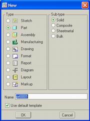
- You should know how to start pro/E and creating a new part by reviewing the Tutorial of Basic Modeling I, follow those commands till step 3, but in this tutorial, give part name by Cylinder.prt.
- Select Revolve tools and sketching tool will appear in bottom of windows and set axis revolution value with 360, make sure that Revolve as solid was select.

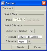
- Press Sketch tool and choose Front Datum Plane as Sketching Plane and Right datum Plane for Right Orientation and then Press Sketch Button on the dialog.
- Make sure that we have vertical and horizontal reference to draw.
- Let’s begin section draw using draw tools and try creating sketched section like below picture. Don’t forget to create axis revolution.
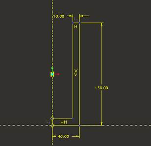
- After you have finished draw and edit the dimension, press OK button and press green checklist button to assign revolve tool.
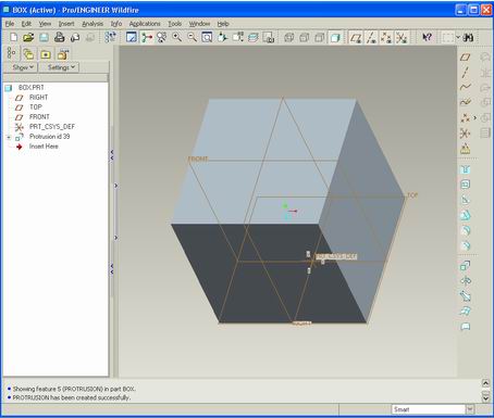
- Your models should look like this picture.
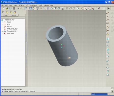
- Congratulation you have been finished basic tutorial II. Don’t forget to save your job.
Note: You can find this teory in PTC Help.
This tutorial create by Ibrahim


