Showing posts with label pro/Engineer. Show all posts
Custom Search

Using Toroidal Bend to create Automobile Tire in Pro/Engineer Wildfire

The ToroidalBend option bends solids, nonsolid surfaces, or datum curves into toroidal (revolved) shapes. (ref: PTC Help).

In this tutor we will create simple automobile tire, feel free your design but for the 1st time follow this design for understanding how to use this feature in Pro/Engineer Wildfire.


1. Create base Feature like this picture and dimension using extrude feature. Create sketch at Front Datum Plane as Sketcher plane and sketch like below picture. After finish sketch, Extrude that sketch 10000mm.

2. Adding grip at tire using extrude feature and use below sketch at top face of base. Enter extrude value 20.

3. Pattern grip feature 9 grip. Click at dimension with value 50, change become 105 and fill in n value with 9. Finish it with click at green checklist.


4. Create Round feature at 4 corner at grip with radius 12. 

5. Create pattern for last round for grip using this method: at model tree, right click round feature and choose pattern. 

6. Create second round at grip feature at lower and upper edge with Radius 3.


7. Create pattern same using step 5 for 9 grip.

8. Create mirror for all body: click Edit -> Feature Operation -> Copy -> Mirror -> All Feat -> Dependent -> Done. Select Right Datum Plane as Mirror Plane -> Done
mirroring base
9. Revolve this body using Toroidal bend and control by tire profile sketch by Click Insert -> Advanced -> Toroidal Bend. Options Popup will appear. Choose 360 -> One Side -> CrvBendContract-> Done -> Select All Solid -> Done. Choose magenta face as Sketch Plane and top surface as Top Plane for sketching curve. 

After finish sketch Click finish button and select parallel face as start and end of revolution toroidal. And finishing by clicking done.
before toroidal bend


after toroidal bend
That All, i hope this tutorial usefull for you

Read More......

How to define material sheet size in Pro/Engineer and UG NX3?

Custom Search

How to define material size for sheet metal bending in Pro/Engineer and UG NX3?


This tutorial use for determine raw material sheet size for bending part.


In this tutorial I used simple part called stabilizer_cover.prt. This is simple part, so you can create this part quickly by yourself.
OK, lets to starting this tutorial in Pro/E wild fire


1. Open Sheet metal part (stabilizer_cover.prt)


2. Click Application at Menu Bar and then choose Sheet metal, pop up menu SMV Convert will appear (this converting part modeling to sheet metal modeling) choose driving srf and determine thickness value (in this tutorial use thickness 0.5 mm), and then press green check list.


3. Now, we on sheet metal environment application with new command for sheet metal. In menu manager click Feature -> Create ->Sheet metal -> Unbend-> Regular -> Done. Select surface as fixed surface, -> Unbend All -> Done. And now you can measure sheet size. Enjoy it…


Now, Let’s Try in Unigraphic NX3

1. Open Sheet metal part (stabilizer cover.prt) then choose click application in menu bar, choose sheet metal -> forming/flattening, Part in Process dialog box appear, Choose OK.


2. In new Environment windows click Tool in menu bar then choose flat Pattern and Flat Pattern Dialog box will appear.

Default selection this dialog box is Unform Sheet Metal Feature, so just pick top surface on your part and Bend Allowance Formula in Flat Pattern Dialog box will active.


3. Click Bend Allowance Formula and Bend Allowance Formula Dialog box appear, choose 1 formula (you can change constant number, as your material reference, i change constant to 0.3183 same with pro/E default setting). Click OK.


4. Click Apply to unform this part. And The Result like below picture.

An the result is 484.637mm x 200mm same with pro/E result.


Read More......

Creating Pattern Following Curve in Pro/E WildFire

Custom Search

In this tutorial, you can make a pattern feature to following curve…

How to make it..?

Here is Steps.

  1. Try to make curve like this shape, in Pro/Engineer Wildfire you can make it by pressing sketch datum curve tool on datum plane.

  2. 2nd step is creating datum point on curve and use Length Ratio Option. And create point pattern using dim length ratio.

Use this relation to make proportional distance on curve.

d1 = 1/(p3+1)

d2=d1

this parameter (d1or d2) depend on your creation, in your work, may be you find different parameter.

  1. Create an Axis trough the first point and tangent to curve.

  2. Create An Datum plane Trough the point and perpendicular to first axis

  3. Try to create revolve feature use the similar datum plane like you make first curve and choose new datum plane just you created as orientation datum plane.

  4. Make a local group for axis, new datum plane and revolve feature.

  5. Pattern the group with option reference.

  6. Mirror all feature by middle datum plane.

  7. Finally your model should look like below picture.


Selengkapnya.....


Read More......

Creating User Define Feature Pattern

Custom Search

Creating user define Pattern using Sketch construction.

Hi, I am back to share my knowledge after vacuum for long time..
Here I try to create pattern (array) using sketch construction to direction array / pattern in Pro/Engineer Wild Fire.

This picture is result pattern construction without variable option pattern.


The First step to creating this technique is creating pad with desire dimension, and then try to sketch feature to cut using like this geometry (see below picture).


After cutting pad, the final step is pattern cut feature did you have just created. Good luck.

With same technique like above but try to add dimension as height of slot to variable pattern height applies for below construction.


Any questions for this technique please send an email to nje_riet@yahoo.com

Read More......

Surface Correction

Custom Search

Tips: Surface Correction.

Hey…, may be you have surface model with broken half or damage, so you can not solidify this surface in pro/Engineers.

Here are tips for correct that surface.

Open your model with damage surface in pro/Engineer wildfire.

Fig.1. damage surface.

Click boundary blend tool (go to insert and click boundary blend) and then pick at first direction field and choose edge pairs then pick second direction field and choose two edge for 2nd direction reference.

Fig. 1st direction field and 2nd direction field

Opposite red edges are edge pairs

After finished correction of broken surface, you can merge with main surface so you can do solidify action.

This is the result.

Feel free to enjoy…

Command please…

Read More......

Tutorial MoldFlow Using Plastic Adviser

Custom Search


How to Use Plastic Advisor in Pro/Engineer?

Introduction

The Adviser is designed to help an engineer determine the manufacturability of plastic part designs.

Cavity models

The Adviser allows you to create a model of your part in a CAD package, and then read the model in to the Adviser.

Analysis preparations

For a Plastic Flow analysis, you need to select the polymer and the injection location. Other settings, such as material temperature and pressure, are automatically selected according to the material’s properties, but you can alter them if you wish.

Additional analyses can also be performed in order to investigate other aspects of part design.

Ok, this is an example of using plastic advisor at upper case of charger for NOKIA. Before you try to analyze a model, I hope you should be understand about designing plastic product, including how to creating rib, how about draft angle, Round Corner, Thickness and other criteria for plastic design.

Step bye Step to Run Plastic Adviser.

Ok, this is the step by step using Plastic Adviser within Pro/Engineer. Enjoy it…


Cavity Model

The first Requirements to run Plastic Adviser are built a model as Cavity. If you have finished your plastic model, you can run Plastic Adviser with the following some ways:

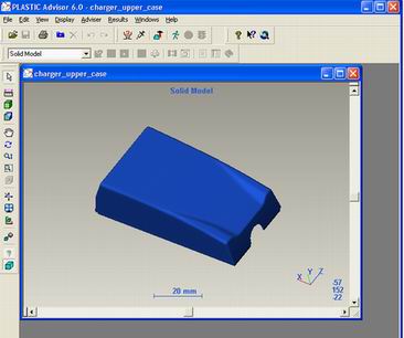
  • Click Application in Menu Bar and then choose Plastic Adviser -> middle click to ignore set injection location in order to determining best injection location in plastic adviser Windows that will appear for a few minutes after you click on middle button.
Plastic Adviser Windows

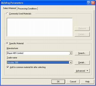
  • After Plastic Adviser Windows was appear, you must set Molding Parameters Such as Material Type, Material Operating Temperature, Mold Temperature, Injection Pressure by click Adviser on Menu Bar and choose molding parameter, and then molding parameters dialog will be appear. For Select Material, you must set plastic manufacturer and choose your material. And then set mold temperature and Injection Pressure in Processing Condition Tab. In this case, I try to use Bayer ABS Limited as Manufacturer and Absolac 300 As trade name with Mold Temperature (60oC), Melt Temp (225 oC), Injection Pressure( 250Mpa), Machine Clamp Open Time (3 sec). See this Picture.
Molding Parameter
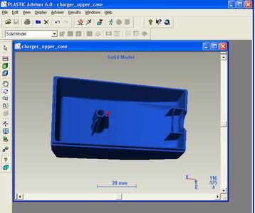
  • Set Injection Location, Please Determine the best location for placement gate. Click Adviser and choose Pick Injection Location and then click where you want to set best location for gate in the cavity model.

Injection Location

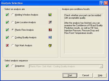
  • Run Analysis; you can select type of analysis based on your needed bye click Adviser -> click Analysis Selection and Then you add check list for type an analysis. This is checking for flow analysis.
Analysis Selection

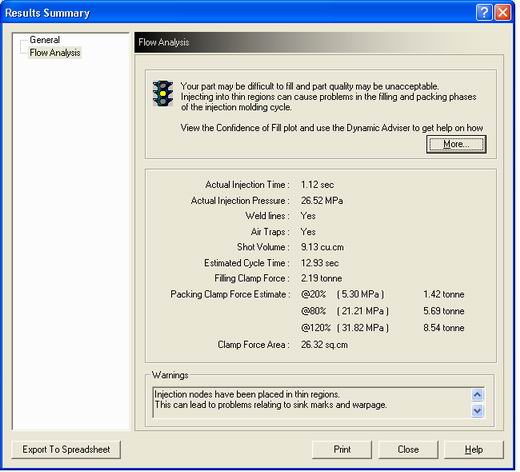
  • Result.
Result Summary

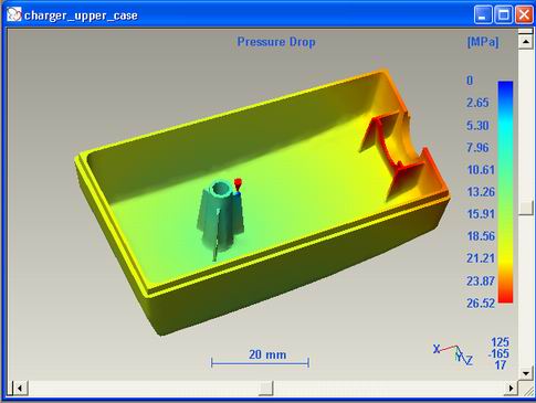
  • You can read result under result menu bar and then you can show type of analysis result. This is sample Pressure drop result.

Sample Result : Preswsure Drop
  • You can view analysis type and solving problem if there are some bad characteristic.

Results

After the Plastic Flow analysis has finished, you can look at the Confidence of Fill result, which is derived from the Fill Time, Injection Pressure, Pressure Drop and Flow Front Temperature results.

A green area has a high confidence rating yellow indicates a medium confidence rating, while red shows a low confidence rating.

Read the Confidence of Fill advice for suggestions on improving a medium or low result. If the Confidence of Fill result indicates problems, look at the other results to find the reason for the low or medium confidence of fill.

If the Confidence of Fill result shows any molding problems, look at the pressure and temperature results to identify where the problem is coming from. After looking at the Confidence of Fill, you should study the air trap and weld line results to find other possible molding problems.

You can then review the inputs and try to resolve any problems. Areas on the part that show low or medium confidence of fill may need to be redesigned or a new material selected for the part to fill.

Once you are confident that the part will fill, you can check the Quality Prediction result, which estimates the expected quality of the part's appearance. To find out more information and possible solutions to any implied problems, use the same methods you used for investigating the Confidence of Fill result. You can also use other analyses available to investigate and solve design problems.

Reference : PTC Help
Tutorial & Model by Ibrahim

Read More......